|
|
IPSentry - Alert - X10 Power Control
The X10 Power Control feature provides you with a
way to control external power sources through the X10 power control modules and
CM11A controller or new CM17A (Firecracker) transmitter.
This is ideal for turning on and off external sirens and alarm lights in and
around the data center providing highly visual and audible alerts to local personnel.
See: http://www.x10usa.com for product
information.
Note: We strongly advise against configuring the X10 alert to power-cycle
computer systems as the potential for data loss due to power loss can be
substantial. This is not intended for use on systems susceptible to damage
due to power fluctuations.
Please see the How-To section for additional information on various configurations.
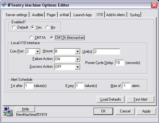
Enabled
This frame provides a tri-state selection regarding the status of the alert
which allows you to enable, disable, or use the global state (default)
Alert Success
All alerts with the exception of paging alerts make use of this setting.
When checked, the alert will be generated both when the system fails an when the
the failure is corrected.
For example, if you are monitoring a web server and it fails, the alert would be
triggered noting that there is a failure. Additional failure notification
will be sent according to the alert schedule outlined below. Once the
system is recovered and the failure corrected, another alert will be generated
as an "UP" notification.
In using alerts such as Pager or Email, the IPSentry Keyword %IPS_M_STAT% will
be converted to the current state of the device making it possible to recognize
immediately whether the alert was triggered due to the system going
"DOWN" or coming back "UP".
CM11A CM17A (Firecracker)
Currently, only the X10 CM11A, CK11A, and CM17A controllers are supported.
Com Port
Enter the communication to which the X10 PC Interface controller is attached.
House
X10 Units are identified by their HOUSE/UNIT code. Each represented by a
unique identity. Enter the House Code of the unit you wish to control.
Unit
X10 Units are identified by their HOUSE/UNIT code. Each represented by a
unique identity. You may enter one or more unit codes (separated by
","). All units entered must have the same house code.
Failure Action
Upon detection of a failure, IPSentry will perform one of the following:
ON - Sends a request to power ON the selected
unit.
OFF - Sends a request to power OFF the selected unit.
CYCLE - Sends OFF, wait the specified number of
seconds, sends ON.
Success Action
When IPSentry detects the monitored device after a failure has been detected,
IPSentry will perform one of the following:
ON - Sends a request to power ON the selected
unit.
OFF - Sends a request to power OFF the selected unit.
CYCLE - Sends OFF, wait the specified number of
seconds, sends ON.
Power On/Off Delay
If using "CYCLE" as a Failure option,
enter the number of seconds that IPSentry wait after powering down the unit
before sending the request to power up the unit.
Alert Schedule
The alert schedule allows you "fine tune" the alerting functions to
avoid unnecessary alerting during an extended failure. You may not want to
be paged every single time a failure is detected after the first alert.
You can use this schedule to set how many failures must be detected before the
first alert. Set how many failures must be detected for each subsequent
alert, and the maximum number of alerts you feel are adequate to obtain a
response from specified personnel.
Note: Setting the first-after or every values to any value less than 1 can have unexpected results.
Load Defaults
(button)
This button will load the default configuration information into the appropriate
fields. This is a quick way to use a standard configuration with minor
variations between entries.
Note: You need NOT use this option when the enabled option is set to
"Default" since the replacement of the alert configuration with
default configuration values will be done automatically when the alert is
triggered. You need only use this button when the enabled option is set to
YES and you wish to slightly modify the default configuration and make the entry
specific to the monitored device to which this alert is related.
Test Alert (button)
This option will attempt to process the alert as configured. A message will be
displayed regarding failure or success of the alert generation.

|
|
||
| Contact: support@ipsentry.com | https://ipsentry.com | © 2006 by RGE, Inc. - All Rights Reserved |